8.0 Boxster Technical Bulletins
[egjhcdfg]
Other Xoc managed sites:
http://www.xoc.net
http://grr.xoc.net
http://www.mayainfo.org
https://mayacalendar.xoc.net
http://www.yachtslog.com
- 0-General
- New Boxster Bulletin Layout and Filing System [grp0 1/96 0000 1/14/97]
- Maintenance Schedule for 1997 Boxster [grp0 1/96a 0300 4/8/97]
- Reporting Boxster OBD II Related Repairs [grp0 1/97 0335 7/3/97]
- Switching off Injection Valves with PST2 Tester [grp0 5/97 0300 8/5/97]
- Assembly and Use of the Hardtop/Wheel Storage System [grp0 3/97 0913 11/18/97]
- Reporting Boxster OBD II Repairs [grp0 9801 0335 3/17/98]
- "Check Engine" Light On [grp0 1/98 03.. 4/2/98]
- Pre-Delivery Inspection and Activation of Porsche Communication Management (PCM) M662 [grp0 8/97 03.. 5/14/98]
- 1-Engine
- Lifetime Antifreeze [grp1 2/96 1938 1/14/97]
- Engine Repairing [grp1 9701 1010 2/4/97]
- Cooling Hose Precautions [grp1 2/97 1962 5/8/97]
- Hose Clamps for Cooling Hoses [grp1 3/97 1962 5/8/97]
- Engine Oil Leaks [grp1 4/97 1359 5/13/97]
- New Type Cooling System Hose Clamps [grp1 10/97 1963 8/14/97]
- Engine Oil Leaks [grp1 4a/97 1359 9/4/97]
- Oil Cooler [grp1 8/97 1740 9/4/97]
- Crankshaft Seal Installation Tool [grp1 9/97 1010 9/4/97]
- New Engine Coolant Bleeder Hose Connections [grp1 11/97 1943 10/21/97]
- Special Tool 9612 Modification [grp1 7a/97 1505 3/19/98]
- Replacing Crankshaft Sealing Ring (with Tools 9609 and 9609/1) [grp1 3/98 1010 5/14/98]
- Magnetization of Valve Tappets [grp1 4/98 1559 5/14/98]
- Engine Repairing - Cylinder Head and Head Gasket [grp1 7/98 1001 5/15/98]
- 2-Fuel/Exhaust
- 3-Transmission
- Manual Transmission Repairs [grp3 9701 3435 2/4/97]
- Tiptronic Transmission Repairs [grp3 9701 3710 2/4/97]
- Manual Transmission Oils [grp3 1a/96 3435 4/24/97]
- Tiptronic Transmission Oils [grp3 1a/96 3... 4/24/97]
- Replacing Manual Transmission [grp3 5/97 3435.. 8/14/97]
- Manual Gearbox - Inspection of Differential Carrier [grp3 9801 298 6/22/98]
- 4-Running Gear
- Non-OEM Wheels/Bolts [grp4 9701 4407 3/4/97]
- Left Front and Right Rear Wheel Carrier Housing [grp4 1/97 4050 5/8/97]
- Cleaning Light Alloy Wheels [grp4 4/97 4412 8/14/97]
- New Brake Pad Material [grp4 3/97 4636 8/26/97]
- Filling of Power Steering Hydraulic Fluid [grp4 5/97 4898 9/30/97]
- Summer Tire/Wheel Summary [grp4 1/96 4440 10/16/97]
- Winter Tires, Wheels, and Snow Chain Applications [grp4 6/97 4440 12/2/97]
- Summer Tire/Wheel Summary [grp4 7/79 4440 4/2/98]
- 5-Body
- 6-Body
- Windstop Retaining Clips [grp6 4/96 6847 1/14/97]
- Installing/Latching Hard Top [grp6 2/96 6102 1/16/97]
- Installation of Cupholders [grp6 5/96 6830 2/25/97]
- Replacing Air Bag Control Unit [grp6 1/97 6968 7/10/97]
- Cover for Cabriolet Rear Window [grp6 7/97 6102 7/31/97]
- Porsche Child Seat Installation [grp6 6/97 USA 6923 8/28/97]
- Closing of the Cabrio Top [grp6 4/97 6102 9/4/97]
- Boxster Roof Transport System [grp6 5/97 6692 9/9/97]
- Air Bag Warning Lamp On [grp6 9701 6924 9/30/97]
- Center Windstop Mounting Brackets [grp6 11/97 6684 9/30/97]
- Installation of Tonneau Cover [grp6 8/97 6157 10/16/97]
- Modifications and Adjustments to Soft Top [grp6 9/97 6128 10/16/97]
- Installation of Hardtop/Speedster Cover Pivot Pin Guides [grp6 1/97 6117 10/28/97]
- Installation of a Speedster Cover [grp6 12/97 6154 12/2/97]
- Extended Storage of Soft Top in Open Position [grp6 4a/97 6102 12/23/97]
- Wind Noise with Hardtop Installed [grp6 3/98 6102 5/14/98]
- New Version Roof Transport System (RTS) and Boxster Hardtop [grp6 5a/97 6692 5/14/98]
- Installation of Roof Cargo Container (with Roof Transport System) [grp6 14/97 6692 5/29/98]
- Improved Sun Visor Mirror Cover [grp6 1/98 6823 5/14/98]
- 8-Service Technical Bulletins
- 9-A/C & Electrics
- Installing Aftermarket Radios [grp9 1/96 9120 1/14/97]
- Cleaning Plastic Components [grp9 3/96 9415 1/14/97]
- Headlight Ventilation [grp9 4/96 9415 1/14/97]
- Requesting Vehicle Security Codes [grp9 9701 9068 2/25/97]
- Replacing Alarm / Drive Block Control unit [grp9 1/97 9093 3/4/97]
- Boxster Interior Monitor Sensor Mounting [grp9 6/97 9685 9/25/97]
- Requesting Vehicle Security Codes [grp9 9801 9068 3/17/98]
- Programming Automatic Relocking and Unlocking of Doors and Rear Lid [grp9 3/98 9687 6/5/98]
- X-Service Technical Bulletins
This section includes information from the Boxster Technical Bulletins. Some are administrative only and are only relevant to Porsche dealers. Others are practically required reading by every Boxster owner. The title and and an annotation about each one is shown below relating the interesting information. You may request complete copies of any of these bulletins from your dealer. Your dealer may charge you for copying and processing fees. All bulletins are copyright by Porsche Cars North America, and the sections quoted here (indented) are reproduced under fair use provisions of copyright law.
Boxster bulletins are broken into groups. Each bulletin is given a group, a month/year number assigned by PAG, a part number, and a release date. A few bulletins are created by PCNA, which uses a numbering system instead of a month/year system for numbering their bulletins. The bulletins below are sorted by release date within a group.
You may order a subscription to all of the Porsche Technical Bulletins. Request this ![]() (click to enlarge)
form from your Porsche dealer's parts counter. Unfortunately, the subscription is a
ridiculous $250 per year. You may also get a compilation of all of the 1997 Porsche
Technical Bulletins by acquiring a book from your parts counter, part number
PNA.000.082.N. Cost is about $18.
(click to enlarge)
form from your Porsche dealer's parts counter. Unfortunately, the subscription is a
ridiculous $250 per year. You may also get a compilation of all of the 1997 Porsche
Technical Bulletins by acquiring a book from your parts counter, part number
PNA.000.082.N. Cost is about $18.
0-General
New Boxster Bulletin Layout and Filing System [grp0 1/96 0000 1/14/97] 1pg
Describes the layout and filing system.
Maintenance Schedule for 1997 Boxster [grp0 1/96a 0300 4/8/97] 2pgs
A reproduction of the maintenance schedule in the owner's manual.
Reporting Boxster OBD II Related Repairs [grp0 1/97 0335 7/3/97] 1pgs
This bulletin is replaced by Reporting Boxster OBD II Repairs [grp0 9801 0335 3/17/98].
Says that if the Check Engine light is lit, that the dealer must submit the entire fault log reported by the OBD II to Porsche along with all parts that were removed.
Switching off Injection Valves with PST2 Tester [grp0 5/97 0300 8/5/97] 1pg
Must have a PST2 Tester for this to be interesting.
Assembly and Use of the Hardtop/Wheel Storage System [grp0 3/97 0913 11/18/97] 5pgs
Describes how to put the unit together, including how the unit can be mounted on the Transport Cart (part number 000.044.000.22) or on the wall with just the Hardtop Holder (part number 000.044.000.21). If you get this unit, get this bulletin as well.
Reporting Boxster OBD II Repairs [grp0 9801 0335 3/17/98] 1pg
This bulletin replaces Reporting Boxster OBD II Related Repairs [grp0 1/97 0335 7/3/97].
Gives the procedure for reporting the OBD II (On Board Diagnostic computer in the car) log to PCNA any time that the "check engine" light comes on.
"Check Engine" Light On [grp0 1/98 03.. 4/2/98] 2pgs
Describes three reasons that the "check engine" light might come on and how to fix them. The three reasons are:
- Dirt in the valve tappets
- Camshaft timing not in specification
- Variocam actuator mechanically faulty
Pre-Delivery Inspection and Activation of Porsche Communication Management (PCM) M662 [grp0 8/97 03.. 5/14/98] 3pgs
Says that the PCM unit is shipped turned off to keep it from draining the battery. It must be turned on using the PST2 computer at the dealer before delivery. It also describes how to enter the security and navigation codes to activate the unit. It also mentions giving the unit some time under an open sky and 31 miles of driving to let the GPS unit calibrate itself each time the battery is disconnected.
1-Engine
Lifetime Antifreeze [grp1 2/96 1938 1/14/97] 1pg
The Porsche Boxster engine cooling system is factory filled with a lifetime antifreeze. The engine coolant is a mixture of 50% antifreeze (silicate free) and 50% water. At this time, only antifreeze available from Porsche is authorized for use in the Boxster.
For top-ups or replacement, only the new antifreeze should be used. In emergency cases where the correct antifreeze is not available and a top-up of the system is necessary, clear water may be used. This will affect antifreeze concentration levels.
Antifreeze concentrations:
50% antifreeze is good down to -30� C (-31� F)
60% antifreeze is good down to -40� C (-40� F)
A higher concentration should not be used as the heat transfer quality of the coolant will decrease.
Part Number 000.043.203.78 Antifreeze in 1 liter container.
Engine Repairing [grp1 9701 1010 2/4/97] 1pg
Says that any engines with internal damage will be entirely replaced until further notice. This is superceded by Engine Oil Leaks [grp1 4/97 1359 5/13/97] and Engine Repairing - Cylinder Head and Head Gasket [grp1 7/98 1001 5/15/98].
Cooling Hose Precautions [grp1 2/97 1962 5/8/97] 1pg
Warns that the coolant hoses must not come in contact with "Pentosin" oil used in the power steering system when refilling. "Pentosin" oil can cause swelling of the coolant hose and damage the hose unless cleaned up with water immediately.
Hose Clamps for Cooling Hoses [grp1 3/97 1962 5/8/97] 1pg
Superceded by [grp1 10/97 1963 8/14/97].
Engine Oil Leaks [grp1 4/97 1359 5/13/97] 2pgs
Supercedes, in part, Engine Repairing [grp1 9701 1010 2/4/97]. Superceded by Engine Repairing - Cylinder Head and Head Gasket [grp1 7/98 1001 5/15/98].
Says how to make internal engine repairs in the area of the flywheel or drive plate for the torque converter.
New Type Cooling System Hose Clamps [grp1 10/97 1963 8/14/97] 1pg
Supercedes [grp1 3/97 1962 5/8/97].
In the area of the Tiptronic transmission, coolant leakage can occur between the cooling system hoses and the metal pipes. The reason is that tolerances between the cooling system hoses and the metal pipes may not allow the spring loaded hose clamps to apply enough tension on the cooling hoses to prevent leakage when the cooling system is under pressure.
Coolant leakage may occur at coolant hose connections due to insufficient tension of the spring type hose clamps. New vehicles are equipped with 1 to 2 mm smaller diameter spring hose clamps as of May 15, 1997 production.
Goes on to describes the various parts to make the repair.
Engine Oil Leaks [grp1 4a/97 1359 9/4/97] 1pg
Talks about how to repair engine oil leaks in the area of the intermediate shaft flange.
Oil Cooler [grp1 8/97 1740 9/4/97] 1pg
Talks about how to make repairs to engines that have two additional O-rings per connection in the oil cooler.
Crankshaft Seal Installation Tool [grp1 9/97 1010 9/4/97] 1pg
Talks about this tool.
New Engine Coolant Bleeder Hose Connections [grp1 11/97 1943 10/21/97] 1pg
Engines as of Model Year '98 (W) have a modified routing of the coolant bleeder pipe from engine to coolant reservoir.
The bleeder pipe will no longer be connected to the top engine coolant housing connection. The new bleeder line will be a hose that is connected to the top of the oil cooler assembly. The new hose is routed around the starter motor and connects to the coolant reservoir coupling hose. The connection and fastening of the hose will be made with the spring-type hose clamps.
Gives the part numbers.
Note: Replacement engine will be equipped with new bleeder hose only.
Special Tool 9612 Modification [grp1 7a/97 1505 3/19/98] 2pgs
Describes how to modify a special tool for aligning the Boxster camshaft timing. It warns:
Failure to modify this tool will result in false cam timing. This fault may lead to chronic "Check Engine" light programs, customer dissatisfaction and possible lemon law action.
Warranty claims may be subject to charge back if repetitive repairs are claimed due to the failure to modify this tool.
Replacing Crankshaft Sealing Ring (with Tools 9609 and 9609/1) [grp1 3/98 1010 5/14/98] 1pg
It says:
To avoid recurring leakage of the crankshaft sealing ring, a replacement crankshaft seal must be installed in a different position.
It then describes the modified tool used to set the crankshaft sealing ring.
Magnetization of Valve Tappets [grp1 4/98 1559 5/14/98] 1pg
Warns that magnetized tools cannot be used when working on the valve tappets, as they can cause the valve tappets to become magnetized.
Engine Repairing - Cylinder Head and Head Gasket [grp1 7/98 1001 5/15/98] 2pgs
Supercedes Engine Repairing [grp1 9701 1010 2/4/97] and Engine Oil Leaks [grp1 4/97 1359 5/13/97].
Lists the parts that the dealer can repair. The dealer can now repair the following:
- Cylinder-head, remove and install
- Cylinder-head disassembly and reassembly
- Cylinder-head gasket replacement
- Engine coolant pump and thermostat
- Engine oil pump
- Cylinder-head oil return pumps
- Oil pan
- Oil cooler
- Flywheel/drive plate
- Engine mounts and brackets
- Rear main seal (rear crankshaft sealing ring)
- Front pulley seal (front crankshaft sealing ring)
- Valve covers, camshafts, and hydraulic lifters (valve tappets)
- O-ring for intermediate shaft flange
- Protective tube for spark plugs
- Engine drive belt
- Exhaust system
- Alternator
It says that when performing cylinder-head repairs, to check the surfaces of the crankcase and cylinder-head for damage or pitting. If excessive damage of the sealing surface exists (such as chips or pitting) replacement of the complete engine will be necessary.
It also says that if there are repairs outside the scope of the components listed above or if engine replacement is necessary that the Technical Service Department and the Porsche District Service Manager be contacted before any work is done.
2-Fuel/Exhaust
Battery Discharge [grp2 1/96 2706 1/14/97] 1pg
If the ignition key is left in the "0" position for long time periods, the vehicle battery can become discharged.
Goes on to say that this leaves the airbag control unit, alarm control unit, combination instrument cluster, radio, and daylight driving lights (M-113 Canada only) still powered.
Therefore, please inform the customer and the Sales and Service Departments to remove the ignition key from the ignition lock when the vehicle is not in use.
Replacing Engine Control Module (ECM) [grp2 1a/97 2470 3/4/97] 2pgs
Describes how to code a new ECM immobilizer code. Not much interesting here unless you are a Porsche tech.
Humming/Vibration Noise from Fuel Return System [grp2 4/97 2458 4/29/97] 1pg
At an ambient temperature near 41� F (+5� C) or lower, a humming/vibration noise may be noticeable after a cold start for approximately 30 seconds.
This noise is caused by oscillations in the fuel system piping. This noise is mainly noticed in the dashboard area or front luggage compartment. As of February 10, 1997, production and engine number 65V 04654, a modified fuel pressure regulator and fuel return line are installed.
In case of customer complaint, the new fuel pressure regulator and fuel line can be installed.
Goes on to describe the parts and labor.
Spark Plugs: Changed Heat Range [grp2 5/97 2870 4/29/97] 1pg
As of the introduction dates listed below the factory is installing spark plugs with a changed heat range (more favorable cold-start behavior).
New: Bosch FR 7 LDC4 or Beru 14 FR 7 LDU
Former: Bosch FR 6 LDC or Beru 14 FR 6 LDU
As of 4/23/97, from Engine Number 65 V 09399
Effective immediately, if spark plug replacement becomes necessary, install the spark plugs with the newly approved heat range. Spark plugs must be of the same heat range in the engine. This applies to engines prior to the above mentioned introduction date.
Part Number: 999.170.201.90 Spark Plug (qty. 6 required)
Installing Tail Pipe [grp2 3/97 2635 9/9/97] 1pg
Describes installation of chromed, special steel tailpipe.
This oval-shaped chromed, special steel tailpipe can be installed in [all Boxsters]. Power output, emissions, and noise are not adversely influenced by this special tailpipe.
Part Number: 986.111.980.00
3-Transmission
Manual Transmission Repairs [grp3 9701 3435 2/4/97] 1pg
Says that until further notice, internal manual transmission problems will be entirely replaced. External components can be repaired or replaced as required.
Tiptronic Transmission Repairs [grp3 9701 3710 2/4/97] 1pg
Says that until further notice, internal Tiptronic transmission problems will be entirely replaced. External components can be repaired or replaced as required.
Manual Transmission Oils [grp3 1a/96 3435 4/24/97] 1pg
Same details as [grp3 1a/96 3... 4/24/97], but normally organized into a different binder at the tech shop.
Only selected transmission oils may be used in the Boxster Tiptronic and Manual transmissions. Use of non-approved transmission oils may lead to excessive transmission wear.
Porsche approved transmission oils may be obtained by ordering the following part numbers. When topping up or changing transmission oils, only use the approved oils listed below.
Manual Transmission Part Number N.052.911.CO Hypoid transmission oil SAE 75W-90 (20 liter container). Transmission fill: 2.25 liter.
Tiptronic Transmission Part Number 999.917.547.00 Automatic transmission fluid (20 liter container). Transmission fill: 9.0 liter. Transmission change: 3.5 liter.
Tiptronic Transmission Final Drive Part Number 999.917.545.00 Hypoid transmission oil SAE 75W-90 (1 liter container). Transmission fill: 0.8 liter.
Tiptronic Transmission Oils [grp3 1a/96 3... 4/24/97] 1pg
Same details as [grp3 1a/96 3435 4/24/97], but normally organized into a different binder at the tech shop.
Replacing Manual Transmission [grp3 5/97 3435.. 8/14/97] 1pg
Just mentions about how to ship back a replaced manual transmission.
Manual Gearbox - Inspection of Differential Carrier [grp3 9801 298 6/22/98] 6pgs
There was a Service Action for certain 1998 model year Boxsters. The manual transmissions of 36 vehicles may have been assembled with incorrect differential gears (beveled spider gears) in the differential carrier of the manual transmission. For these 36 vehicles, the transmission must be checked, and if found to be out of specs, the transmission must be replaced. All known owners of these cars will be notified by First Class Mail the week of June 22, 1998. If Porsche doesn't have the information on the owner of the car, the selling dealer will be notified.
The 36 VINs involved with this action are listed below:
| WPOCA298XWU622900 | WPOCA298XWU622902 | WPOCA298XWU622903 | WPOCA298XWU622904 |
| WPOCA298XWU622905 | WPOCA298XWU622910 | WPOCA298XWU622913 | WPOCA298XWU622914 |
| WPOCA298XWU622919 | WPOCA298XWU622921 | WPOCA298XWU622928 | WPOCA298XWU622951 |
| WPOCA298XWU622952 | WPOCA298XWU622954 | WPOCA298XWU622957 | WPOCA298XWU622959 |
| WPOCA298XWU622960 | WPOCA298XWU622962 | WPOCA298XWU622963 | WPOCA298XWU622964 |
| WPOCA298XWU622966 | WPOCA298XWU622967 | WPOCA298XWU622970 | WPOCA298XWU622976 |
| WPOCA298XWU622982 | WPOCA298XWU622988 | WPOCA298XWU622989 | WPOCA298XWU622990 |
| WPOCA298XWU622994 | WPOCA298XWU622998 | WPOCA298XWU622999 | WPOCA298XWU623006 |
| WPOCA298XWU623007 | WPOCA298XWU623013 | WPOCA298XWU623014 | WPOCA298XWU623078 |
4-Running Gear
Non-OEM Wheels/Bolts [grp4 9701 4407 3/4/97] 1pg
Use of aftermarket wheels or wheel accessories (spacers etc.) or non-OEM wheel bolts on Boxster vehicles is not approved.
Only the standard wheel bolts can be used to securely mount the wheels to the vehicle. Boxster wheel bolts with rotating spherical collars are a special design and made from a correspondingly selected alloy for compatibility with standard wheels.
Endurance tests have shown that conventional, commercially available non-OEM bolts can loosen when the car is driven, even if they were installed and tightened to the specified torque.
Eighteen inch wheels are not approved for use on Boxsters. Use of eighteen inch wheels on Boxsters under severe conditions may result in structural failures of the body and/or suspension.
Left Front and Right Rear Wheel Carrier Housing [grp4 1/97 4050 5/8/97] 2pgs
On a small number of vehicles, the mounting area for the wheel speed sensor was machined too far, therefore a 0.5 mm spacer, part number, 964 094 400 99 was glued to the mounting flange to bring the sensor out to the correct depth. Approximate 30 vehicles were produced without the spacer glued to the mounting flange (Figure 1).
The affected wheel carriers can be identified by a date stamp from the following range: (6L14 to 6L25). The date stamp can be seen on the wheel carrier housing at the lower part of the brake caliper mounting bolts. These wheel carrier housing should not be replaced for this specific reason, however, if the wheel carrier or the wheel speed sensor needs to be replaced because of damage, the following procedure should be followed.
Note: Only wheel carrier housings with properly machined wheel speed sensor flanges (no shim installed) are available as spare parts.
Goes on to describe how to replace the wheel carrier housing, both with and without the shim.
Cleaning Light Alloy Wheels [grp4 4/97 4412 8/14/97] 1pg
When wheel cleaning is required, only the Porsche recommended light alloy wheel cleaner can be used to safely clean the wheels. The use of unauthorized alloy wheel cleaners may result in chemical reactions causing corrosion of the wheel bolts and/or locks.
Part Numbers:
999.901.030.40 Cleaner for light alloy wheels (500 ml spray bottle)
999.901.031.40 Refill (1000 ml)
New Brake Pad Material [grp4 3/97 4636 8/26/97] 1pg
A new front brake pad material has been introduced in production. This material has a higher resistance to corrosion when the vehicle has been parked for long periods of time.
The new front brake pad was introduced into production as of April 3, 1997 from VIN: 98X VS 622804.
The old and new version brake pads cannot be installed together. Only brake pads of the same material can be installed on the same axle.
The brake pads can be identified by the following part number on the back of each pad:
New Version: 986.351.930.14
Old Version: 986.351.930.11
New version front brake pad set, part number 986.351.939.13
Filling of Power Steering Hydraulic Fluid [grp4 5/97 4898 9/30/97] 1pg
If work is performed on the power steering system that involves adding Pentosin fluid or refilling the power steering reservoir, car must be taken to insure the hydraulic pump does not run dry.
Then tells how.
When filling the Power Steering System always use Pentosin CHF-11S fluid.
Summer Tire/Wheel Summary [grp4 1/96 4440 10/16/97] 3pgs
This bulletin is entirely superceded by Summer Tire/Wheel Summary [grp4 7/79 4440 4/2/98].
Winter Tires, Wheels, and Snow Chain Applications [grp4 6/97 4440 12/2/97] 4pgs
Summer and winter tires have opposite, seasonal, and specific applications. This is particularly true for high performance Porsche vehicles equipped with wide "ZR" tires designed for safety on dry and wet roads.
The cold weather performance of summer tires is not adequate for winter conditions and their use is discouraged under those conditions.
Summer tires at temperatures below 5� Celsius (41� F) exhibit a decrease in their ability to adhere to the road surface. Installation of the approved winter tire/wheel combinations during cold weather conditions is strongly recommended.
Approved Winter Tires and Types
Tire Size Manufacturer/Type Installation/Comments Application 205/55 R16 89H M+S and 225/50 R16 92H M+S Dunlop SP Winter Sport M2 Uni-directional A 205/55 R16 89H M+S and 225/50 R16 92H M+S Pirelli Winter 210 Asimmetrico Side-directional A 205/50 R17 89H M+S and 225/45 R17 90H M+S Dunlop SP Winter Sport M2 Uni-directional A 205/50 R17 89H M+S and 225/45 R17 90H M+S Pirelli Winter 210 Asimmetrico Side-directional A 205/50 R17 89H M+S and 255/40 R17 94H M+S Dunlop SP Winter Sport M2 Uni-directional A Application A = for all conditions
Tires of the same make and type can only be used on a vehicle.
Observe tire markings on side wall for correct mounting: Arrow with inscription "Rotation" = uni-directional mounting. Inscription "Inside" or "Outside" = side-directional mounting.
Inflation pressure
Axle Wheels Front Axle 2.0 bar (29 psi) Rear Axle 2.5 bar (36 psi) The above fill pressures are valid only for tires approved by Porsche. The tire pressures must be checked and adjusted cold (approx. 20� C/68� F). The values listed cannot be lower under any circumstances.
Approved Winter Tires and Wheel Sizes
Tires Wheels Offset (mm) Axle Snow Chain Part Number 205/55 R16 89H M+S 6J x 16 50.0 front 225/50 R16 92H M+S 7J x 16 40.0 rear 911.361.918.00 205/50 R17 89H M+S 7J x 17 55.0 front 225/40 R17 90H M+S 8.5J x 17 50.0 rear 911(993?).361.931.00 205/50 R17 89H M+S 7J x 17 55.0 front 255/40 R17 94H M+S 8.5J x 17 50.0 rear no snow chains possible Wheels
Overview of Porsche wheels for use with winter tires. The wheel description (wheel size, offset, part number and Porsche trademark) is indicated on the inside and outside of the wheel).
The same wheels as shown for summer tires are approved.
Wheel Fastening
Secure the wheels to the hub with five (5) Porsche lug bolts M14 X 1.5 (19mm socket size). Tightening torque 130 Nm (96 ft/lb).
Snow Chains
The following snow chains are offered by Porsche as accessories:
Tire Size Porsche Part Number Snow Chain Type 225/50 R16 911.361.918.00 Quick, and Stationary mounting 225/45 R17 993(911?).361.931.00 Quick, and Stationary mounting Observe the tire chain installation instructions.
For safety reasons, snow chain equipped vehicles may not be operated at speeds above 30 mph (50 km/h). Always observe local laws and ordinances.
Information
- Porsche recommended winter tires are exclusively "H" tires (210 km/h/130 mph speed rating).
The other recommendations are the same as for summer tires.
Summer Tire/Wheel Summary [grp4 7/79 4440 4/2/98] 6pgs
This bulletin supercedes Summer Tire/Wheel Summary [grp4 1/96 4440 10/16/97].
Approved Summer Tire Manufacturers and Types
Tire Size Manufacturer Type Comments 205/55 ZR16 and 225/50 ZR16 Bridgestone S-02 N3 uni-directional 205/55 ZR16 and 225/50 ZR16 Continental Sport Contact N1 side-directional 205/55 ZR16 and 225/50 ZR16 Michelin MXX3 Pilot SX N2 DOT marking outboard 205/55 ZR16 and 225/50 ZR16 Yokohama AVS S1-Z N1 side-directional 205/50 ZR17 and 255/40 ZR17 Bridgestone S-02 N3 uni-directional 205/50 ZR17 and 255/40 ZR17 Continental Sport Contact N1 side-directional 205/50 ZR17 and 255/40 ZR17 Michelin MXX3 Pilot SX N1 DOT marking outboard 205/50 ZR17 and 255/40 ZR17 Pirelli P-ZERO Direzionale N2 uni-directional 205/50 ZR17 and 255/40 ZR17 Pirelli P-ZERO Asimmetrico N2 side-directional 225/40 ZR18 and 265/35 ZR18 Bridgestone S-02 N2 uni-directional 225/40 ZR18 and 265/35 ZR18 Continental Sport Contact N1 side-directional 225/40 ZR18 and 265/35 ZR18 Michelin Pilot Sport N0 uni-directional 225/40 ZR18 and 265/35 ZR18 Pirelli P-ZERO Asimmetrico N2 side-directional
Notes regarding Pirelli P-ZERO tires N1 and N2:
If installing Pirelli P-ZERO N2 tires, use only on the following axles:
Direzionale N2 = front axle installation only
Asimmetrico N2 = rear axle installation only
Important: 18 inch wheels are only approved for the 986 of of model year 1998 (W)!
The installation of spacer rings to increase a vehicle's track width or to equalize offset is not recommended by Porsche. Porsche will accept no liability for damage resulting from the use of non-approved spacer rings. Please inform your customers about the hazards of such installations.
Do not perform any aftermarket installations.
"N0", "N1", "N2", "n3" indicates a specification identification of the tires. The complete "N" number must be present and visible on the outside of the tire side wall near the type-designation. Only use tires of the same manufacturer, tire type and "N-" specification on one vehicle.
Observe tire markings on side wall for correct mounting:
Arrow with inscription "Rotation" = directional
Inscription "inside\outside" = side-directional
When markings are omitted on the side wall, mount the tire in such a manner that the DOT inscription is visible from the curb side.
Tire pressure
Axle Wheels Emergency Spare Front Axle 2.0 bar (29 psi) 4.2 bar (60 psi) Rear Axle 2.5 bar (36 psi) 4.2 bar (60 psi) The above fill pressures are valid only for Porsche approved tires measured while cold (approximately 20� Celsius/68� F). The measured tire pressures must never fall below those given above.
Approved Summer Tire and Wheel Dimensions
Tires Wheels Offset (mm) Axle Note 205/55 ZR 16 6J x 16 50.0 front 225/50 ZR 16 7J x 16 40.0 rear 205/50 ZR 17 7J x 17 55.0 front 255/40 ZR 17 8.5J x 17 50.0 rear No snow chain installation possible 225/40 ZR 18 7.5J X 18 50.0 front 265/35 ZR 18 9J X 18 52.0 rear No snow chain installation possible Overview of Porsche Rims for Summer Tires
The rim description is located on the inner or outer rim face (i.e.; wheel size, offset (ET), part number and Porsche trademark).
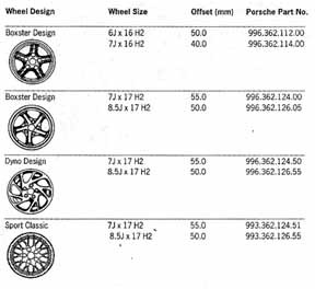
[Editor's note. A new scan including the additional wheel types is coming. This scan from the older technical bulletin.]
Wheel Fastening
Securing of the wheels to the hub occurs with five lug bolts M14 x 1.5 (19 mm socket size). Tightening torque = 130Nm (95 ft/lb).
Information
- At each tire change a new rubber valve stem (part number 900.265.001.50 or 000.044.600.00 including cap) must be installed.
- Observe tire mounting instructions regarding direction of rotation and/or side direction when mounting. Use lubricant to facilitate mounting and to prevent damage to tire beads. Avoid extreme acceleration and braking for the first 60 to 120 miles to prevent tire movement on the wheel. Wheel balancing accuracy may be affected if this should occur.
- Optimal wheel balancing and minimal tire noise can be achieved by matching the tire run out to the wheel. Please refer to the following comments on controlled and uncontrolled matching.
- Uncontrolled matching: If required, move tire on wheel by 90 or 120 degrees to find acceptable values regarding out of round conditions, imbalance, and wheel balancing weight application.
- Controlled matching: Use balancing equipment when matching program capability. Values can be optimized.
- Maximum permissible axial and lateral run out of wheels <= 0.7 mm.
- Maximum permissible axial and lateral run out of tire and wheel assembly <= 1.25 mm (desired value <= 1.0 mm).
- During tire mounting the pressure in the tire should not exceed 4.0 bar (58 psi).
- When new tires are mounted on one axle always use a matched set from the same tire manufacturer with the same "N" designation. The handling characteristics of the vehicle may be affected by differing tread depths between front and rear axle tire sets. The effect is especially true when the rear tire set has been replaced. Use caution during break in of tires.
- When replacing a single tire on an axle, the difference in tread depth may not exceed 30%.
- Repairs on ZR tires and use of tire tubes are not allowed
- The chemical and physical properties of a tire may be affected by long storage time, and the rubber compound may harden over time. Tires which are in constant use or motion will maintain a pliable compound and delay the hardening process. Therefore, the concern should not only be tread depth but the age of the tire as well. Tire should not be older than six years from date of manufacture (includes spare tire). The tire age can be determined from the DOT stamp on the outside of the tire sidewall. For example, "DOT...067" = week 6, 1997.
- Generally tires should be stored in a cool, dry, and well ventilated area. Keep away from sunlight. Avoid contact with fuels, grease, oils, and other chemicals.
- Complete tire/wheel assemblies can be stored horizontally. It is recommended that they be inflated 0.4 bar above the recommended pressure.
- Unmounted tires are best stored in a vertical position. When storing tires in a vertical position, it is recommended to rotate the tires every 2 weeks to prevent any flat spots from developing. When unmounted tires are stored horizontally, they deform severely and will be difficult to mount on the rim flange.
- Optimal conditions for tire/rim assembly storage are offered by the Original Porsche Transport Carrier, part number 000.044.000.22.
5-Body
Front and Rear Hood Release Inoperative [grp5 1/96 5510 1/21/97] 1pg
Should the front and rear hood releases become inoperative due to a disconnected or discharged battery, the following procedure will allow the hoods to be operated electrically under these conditions.
- Open the left door.
- Using an external battery, connect the negative lead to the door stop.
- Connect the positive lead to both sides of fuse "C3" (see illustration below).
- With the door open, move the door latch with a screwdriver into the closed position.
- Using the key, lock and unlock the door.
- The front and rear hood releases can now be operated.
Note: If the vehicle is in the workshop and the battery must be disconnected, try to park the vehicle in a safe area where it is not necessary to latch the front hood.
The diagram shows the same stuff as the bulleted directions above except it shows putting a 30 amp fuse between the external battery positive terminal and the C3 fuse.
Potential for Injury [grp5 3/97 5717 9/9/97] 1pg
If repairs to the door locks, door handles, or door window mechanisms are required and the vehicle battery is connected, be sure to remove fuse #1 in row D. The reason for this precaution is because of the comfort feature of the "automatic window lowering" of the Boxster windows. This feature could be activated unintentionally while working on the door locks, door handles, or door window mechanisms, and injury to hand or fingers could occur if caught in the window opening.
6-Body
Windstop Retaining Clips [grp6 4/96 6847 1/14/97] 1pg
In certain seat positions, the retaining tabs of the left or right side windstops (M-551) may come in contact with and cause damage to the seat backs in the area of the headrests.
To eliminated the possibility of seat damage, remove the left and right side Windstop panels whenever the Cabrio top is closed or the hard top is installed.
If the vehicle is operated with the top down, select a seat position such that the seat backs do not contact the retaining tabs of the left or right side Windstops. If this is not possible because of the height of the driver or passenger, the Windstops should be removed.
New Windstops with modified retaining tabs are currently being developed. When these parts are available, you will be notified.
Installing/Latching Hard Top [grp6 2/96 6102 1/16/97] 1pg
When the hard top is installed and the rear pivot locks are engaged, the windshield frame latch must be fully and correctly engaged into the latch hook receiver and locked securely. This will electrically disable the Cabriolet top drive mechanism.
If the front latch is not secured or left disengaged and the Cabriolet top switch is operated, the Cabrio top storage compartment cover and related parts will be damaged.
Please inform your customers accordingly.
Installation of Cupholders [grp6 5/96 6830 2/25/97] 1pg
Shows how to mount the Boxster cup holders on the air vents.
Replacing Air Bag Control Unit [grp6 1/97 6968 7/10/97] 1pg
Just a bunch of precautions to avoid setting off the airbag when replacing the control unit.
Cover for Cabriolet Rear Window [grp6 7/97 6102 7/31/97] 1pg
Effective immediately, vehicles equipped with a hardtop from the factory receive a protective fleece covering on the Cabrio rear window. This fleece covering will help protect against possible damage to the soft rear window during first time use.
If the hardtop is removed and the Cabrio top is closed, the fleece can then be removed because it will then no longer be necessary.
Please inform your Sales personnel accordingly.
As of June 27, 1997 production.
Porsche Child Seat Installation [grp6 6/97 USA 6923 8/28/97] 3pgs
Instructions for how to install the child seat in conjunction with the deactivation of the passenger side air bag. If you have or want a child seat you might want to read this one for the technical details. It's quite involved to install it. I'll post more on this later.
Closing of the Cabrio Top [grp6 4/97 6102 9/4/97] 1pg
When closing the Cabrio Top for the first time after driving for extended period of time with the Cabrio Top open or hardtop installed, it may be necessary to assist the top by hand during the closing procedure.
The folding top has to go through an initial stretching before it will close without assistance.
Please notify all appropriate personnel and inform your customers accordingly.
Boxster Roof Transport System [grp6 5/97 6692 9/9/97] 3pgs
A roof transport system (RTS) is now available for the Boxster. The RTS can be used to transport large items, or when used with additional attachment modules, bicycles, skis, and surfboards can be safely transported.
The RTS can be used with open cabrio top, closed cabrio top and hardtop, however, if the cabrio top is open or closed it must not be operated with the RTS installed on the vehicle. It is recommended to remove fuse #3 in row D to prevent operation of the cabrio top while the RTS is installed.
The installed RTS and any installed modules should be checked for correct seating and tightness before each trip and on a periodic basis during longer trips. If necessary, fastening hardware should be retightened.
Due to the higher center of gravity and increased surface area exposed to the wind, the vehicles handling changes, therefore, driving of the vehicle should be adjusted accordingly.
Carried items should not extend beyond the RTS support area and must not exceed the vehicle width. All carried items, especially heavy items should be carried as low as possible on the RTS and distributed as evenly as possible over the support area. Items should be secured so not to shift on the RTS during transportation.
If the the RTS is not used, it is advisable to remove it from the vehicle.
Please advise your customer accordingly.
The next two pages describes the actual mounting process and might be worthwhile to see if you have a RTS.
Air Bag Warning Lamp On [grp6 9701 6924 9/30/97] 2pgs
When diagnosing Airbag Warning Lamp on and the fault codes are DTC 44, 45, 46, or 50 Drivers side and/or DTC 47, 48, 49, or 51 Passenger side, the faults may be caused by poor connection at pins B7 and B8 of plug connections X16 and X17. The wiring connections have been corrected as of VIN WPOCA2983WS620157 and the belt buckles as of VIN WPOCA298XWS620138.
The rest of it describes how to replace the wiring connections and belt buckles.
Center Windstop Mounting Brackets [grp6 11/97 6684 9/30/97] 1pg
Just describes that the mounting bracket clips that hold the Windstop in place are now available a spare parts. P.N. 986.561.737.00.01C for the left side and P.N. 986.561.738.00.01C for the right side.
Installation of Tonneau Cover [grp6 8/97 6157 10/16/97] 4pgs
Tonneau covers may now be retrofitted on to Boxster vehicles. The cover can be used as a complete cover (parked car) or fitted only to the passenger side (driving vehicle).
The cabriolet top must not be operated with the tonneau cover installed. A deactivation clip can be installed in the top lock latching assembly to ensure the cabrio top is not operated unintentionally.
The driver's and passenger's doors must not be opened with the tonneau cover installed. The Tenax fasteners or tonneau cover could be damaged. Locking the driver's and passenger's door will help ensure this does not happen.
It goes on to describe the mounting process and the process for the customer installing and removing the cover.
Modifications and Adjustments to Soft Top [grp6 9/97 6128 10/16/97] 3pgs
Describes what to do to fix it if the soft top material is running to the outside or running to the inside.
Some notes:
Before and after production dates April '97 to June 1997, the slider was secured with a pop rivet and pin.
Improved guiding of the top as of January 14, 1997: Longer slider, Pulling strips with piping on the top material have extended on the top. The elastic strip on the top has been deleted.
Additional changes as of July 2, 1997: Elongated hole for the slider guide was increased by 0.7 mm to 11.5 mm. Surface areas on the slider area of the elongated hole have been ground to eliminate damage to the slide foil.
Only the longer slider is supplied for repairs. Also, only the new top with the longer pulling strips will be supplied for repairs.
The longer slider can be installed in earlier vehicles, if at the same time, a new top is also installed. If a new top is not installed the longer slider must be shortened.
It then describes what must be done to shorten it.
Installation of Hardtop/Speedster Cover Pivot Pin Guides [grp6 1/97 6117 10/28/97] 2pgs
Whenever a hardtop or Speedster cover is installed other than a production installation, the new pivot pin guides must also be installed. The pivot pin guides and bolts come with the hardtop or Speedster cover, however, they are also available separately.
The rest describes how to install them.
Installation of a Speedster Cover [grp6 12/97 6154 12/2/97] 5pgs
The Speedster cover can be installed on the vehicle with the top fully opened (Figure 1). The cover is secured using the inserts for the hardtop. After removal of the Speedster cover, separate the cover in the center and place each cover section into the provided fabric pockets. The individual pieces can then be stored in the rear luggage compartments.
The convertible top must not be operated when the Speedster cover is installed. To eliminate the possibility of the top being operated when the cover is in place the red deactivating clip included with the Speedster cover kit must be install. Insert the clip into the slot for the top security hook (above the inside rear view mirror).
It then describes the installation process.
Extended Storage of Soft Top in Open Position [grp6 4a/97 6102 12/23/97] 1pg
When opening the soft top, the flexible rear window must roll uniformly along its entire width. This will ensure that the top folds without developing creases. If necessary, open the top halfway and smooth the roll by hand.
Caution: The ignition switch must be turned OFF before the rear window is smoothed by hand. The soft top rocker switch must not be operated when working on the soft top. There is danger of injury from the soft top or the soft top storage cover mechanism.
It is recommended that sales and parts personnel inform their customers of the above procedure. It is also recommended that service personnel inform the customer of the procedure after installing a hardtop or Speedster cover.
Failure to follow these procedures and creasing of the flexible rear window due to prolonged storage are not a warranty matter.
Wind Noise with Hardtop Installed [grp6 3/98 6102 5/14/98] 3pgs
This bulletin affects cars shipped with a hardtop produced before July of 1997, with a VIN earlier than 986VS25601. If there is excessive wind noise coming from the hardtop B pillar, additional hardtop foam seals can be applied to the hardtop. The rest of the bulletin describes the process of installing them.
New Version Roof Transport System (RTS) and Boxster Hardtop [grp6 5a/97 6692 5/14/98] 1pg
The Boxster Hardtop may be found in three versions:
- Hardtop with backing plates (X2) and painted plastic trim (X2)
- Hardtop with only painted plastic trim (X2)
- Hardtop without backing plates or plastic trim (newest version)
Because of these changes, the RTS mounting procedure has changed. When mounting the RTS to a Boxster, one of the assembly procedures in the technical bulletin Boxster Roof Transport System [grp6 5/97 6692 9/9/97] should be deleted. The mounting procedure for Boxsters with Hardtop or Cabriolet is now the same procedure.
RTS Systems produced from January 1998 do not contain the hardware (adapters and countersunk screws) to allow for RTS mounting directly to the Hardtop, therefore, mounting is attached to the B-pillar area shown in Figure 5 of the above mentioned technical bulletin.
Installation of Roof Cargo Container (with Roof Transport System) [grp6 14/97 6692 5/29/98] 3pgs
Describes how to install the Roof Cargo Container (000.044.000.35) on the Roof Transport System. The Roof Cargo Container mounts to the RTS, and provides for an additional 10.6 cubic feet of cargo space. It can hold 75 Kg worth of material.
Notes provided:
- Periodically check the RTS and Roof Cargo Container to ensure they are securely fastened to the vehicle.
- The weight distribution and aerodynamic cross-section of the Roof Cargo Container may affect the driving characteristics of the vehicle. Driving style must be adjusted to the altered driving characteristics of the vehicle when the Roof Cargo Container is in place.
- Always observe the instructions in the Owner's Manual.
- For maximum driving comfort and fuel economy remove the Roof Transport System and Roof Cargo Container when not in use.
- It is recommended to always seek the assistance of a second person during installation or removal of the Roof Transport System or the Roof Cargo Container.
- When cleaning the Roof Cargo Container, use only mild soap and water. The use of solvents or adhesives may lead to damage of the finish.
- Inform the Owner of the care, cleaning, and safety procedure.
- Keys that are lost can be ordered from the Parts Department.
Improved Sun Visor Mirror Cover [grp6 1/98 6823 5/14/98] 1pg
The cover for the Sun Visor Mirror has been improved as of production date: October 13, 1997, and VINs 98-WS620827 and 98_WU620210. The Sun Visor Mirror assembly is now available individually for mirrors without illumination. Therefore it is no longer necessary to replace the complete sun visor. The illuminated mirror still requires replacement of the entire sun visor should the mirror illumination or cover fail.
The mirror assembly (non-illuminated only) can be replaced by gently prying on the left and right sides of the mirror with two small plastic spatulas. Install the new mirror assembly by carefully pressing it into the sun visor until fully engaged.
Part Number 986.731.901.02.01C.
8-Service Technical Bulletins
Climate Control System-Refrigerant 134a Use [grp8 10/97 8703 4/10/98] 1pg
Talks about replacing the refrigerant used in the climate control system. The only type approved in Porsches is type R134a. R12 substitute refrigerants are not approved and are not considered a warranty matter.
Cover for Spring Strut Mount, Air Conditioning Impaired (Service Action 098) [grp8 3/97 098 3/5/98] 5pgs
This affects a select range of 1997 Model Year Boxsters. Each of the passenger compartment ventilation openings over the cross member in the luggage compartment were covered by an imitation leather cover. The imitation leather cover must be removed and discarded, as it can impair the function of the air conditioning air circulation.
All vehicles listed in the campaign announcement must be checked, and corrected if necessary the next time the vehicle is in the workshop.
PCNA will notify all known vehicle owners directly by First Class Mail during the week of March 16, 1998.
Affected U.S. and Canadian Vehicles by VIN:
| WPOCA2988VS620167 | WPOCA2986VS620233 | WPOCA2981VS620253 | WPOCA2988VS620279 |
| WPOCA2983VS620562 | WPOCA2980VS620700 | WPOCA2982VS621203 | WPOCA2987VS621424 |
| WPOCA2984VS621493 | WPOCA298XVS621515 | WPOCA2980VS621569 | WPOCA2989VS621702 |
| WPOCA2984VS621722 | WPOCA2986VS621785 | WPOCA2989VS621845 | WPOCA2989VS621926 |
| WPOCA2985VS621938 | WPOCA2985VS621955 | WPOCA2989VS621957 | WPOCA2988VS622016 |
| WPOCA2981VS622018 | WPOCA2980VS622091 | WPOCA2983VS622120 | WPOCA2989VS622171 |
| WPOCA2984VS622191 | WPOCA2981VS622195 | WPOCA2989VS622199 | WPOCA2984VS622207 |
| WPOCA2988VS622226 | WPOCA2989VS622235 | WPOCA2984VS622241 | WPOCA2988VS622243 |
| WPOCA298XVS622244 | WPOCA2982VS622254 | WPOCA298XVS622275 | WPOCA2985VS622281 |
| WPOCA2984VS622286 | WPOCA2988VS622288 | WPOCA2986VS622306 | WPOCA2988VS622307 |
| WPOCA2987VS622315 | WPOCA2985VS622328 | WPOCA2984VS622336 | WPOCA2981VS622343 |
| WPOCA2985VS622359 | WPOCA2988VS622405 | WPOCA2985VS622412 | WPOCA2987VS622413 |
| WPOCA2988VS622419 | WPOCA2981VS622469 | WPOCA2983VS622487 | WPOCA2983VS622490 |
| WPOCA2981VS622522 | WPOCA2985VS622586 | WPOCA2989VS622588 | WPOCA2989VS622591 |
| WPOCA2980VS622592 | WPOCA2981VS622603 | WPOCA2980VS622611 | WPOCA2983VS622618 |
| WPOCA2987VS622637 | WPOCA2984VS622644 | WPOCA2986VS622645 | WPOCA2988VS622646 |
| WPOCA298XVS622647 | WPOCA2981VS622648 | WPOCA2983VS622649 | WPOCA2988VS622694 |
| WPOCA2981VS622701 | WPOCA2983VS622702 | WPOCA2989VS622705 | WPOCA2984VS622711 |
| WPOCA2988VS622713 | WPOCA2981VS622715 | WPOCA2985VS622717 | WPOCA2985VS622720 |
| WPOCA2987VS622721 | WPOCA2982VS622724 | WPOCA2986VS622726 | WPOCA298XVS622728 |
| WPOCA2981VS622729 | WPOCA298XVS622731 | WPOCA2985VS622734 | WPOCA2986VS622743 |
| WPOCA2981VS622746 | WPOCA298XVS622762 | WPOCA2983VS622764 | WPOCA2989VS622767 |
9-A/C & Electrics
Installing Aftermarket Radios [grp9 1/96 9120 1/14/97] 1pg
All factory installed radios with sound package M-490 are synchronized with the amplifier. If an aftermarket radio is installed in a vehicle equipped with sound package M-490, the following should be noted:
1-The aftermarket radio must have 2 volts on the preamp-out connection. The M-490 sound package can only be connected and operated using this output.
2-Aftermarket radios having less than 2 volts at the preamp-out connection will have insufficient volume.
Cleaning Plastic Components [grp9 3/96 9415 1/14/97] 1pg
No chemical cleaning agents (spot remover, gas or tar remover) should be used to clean plastic components such as tail lenses or headlight lenses. Cracks may develop in the plastic lenses which would let water into the assemblies.
When cleaning plastic components such as headlight covers or tail lenses only mild soapy water or car wash shampoo should be used.
Headlight Ventilation [grp9 4/96 9415 1/14/97] 1pg
With a combination of weather, temperature, and humidity conditions, the plastic headlight covers may become fogged with moisture for a short time.
The headlight system is vented through the electrical connectors by plastic pipes that extend under the vehicle. When the vehicle is driven, air is drawn through the headlight assemblies via the plastic pipes.
If the headlight covers are fogged, only a short driving time is needed to clear them. Since this condition causes no negative effects, headlight assemblies should not be replaced when fogging occurs.
Requesting Vehicle Security Codes [grp9 9701 9068 2/25/97] 1pg
Superceded by Requesting Vehicle Security Codes [grp9 9801 9068 3/17/98].
Replacing Alarm / Drive Block Control unit [grp9 1/97 9093 3/4/97] 2pgs
Talks about how to code these units if they have to be replaced.
Boxster Interior Monitor Sensor Mounting [grp9 6/97 9685 9/25/97] 1pg
False alarm activation from the Passenger Compartment Monitor Sensor may be caused by the bottom plate of the sensor touching 2 locating pins in the front frame. The 2 locating pins have been shortened as of April 18, 1997 production from VIN 986 VS 623312.
It then describes how to fix it.
Requesting Vehicle Security Codes [grp9 9801 9068 3/17/98] 1pg
Supercedes Requesting Vehicle Security Codes [grp9 9701 9068 2/25/97].
Tells how a dealer can request the immobilizer, teaching, and DME programming codes for a car. A form must be submitted with a lot of details, then Porsche sends the info back. It also says that key cutting codes are obtained through the dealer's Parts Department.
Programming Automatic Relocking and Unlocking of Doors and Rear Lid [grp9 3/98 9687 6/5/98] 1pg
For Model Year 1998 and later Boxsters, it is possible to program the alarm/immobilizer control unit for various unlocking and relocking modes of the doors and rear lid. The time before the doors or rear lid relock automatically can be set anywhere between 4 seconds and 140 seconds. The factory setting for the relocking function is 60 seconds for the doors and 16 seconds for the rear lid.
The automatic rear lid release can also be set to function in one of two version (Software I32) They are:
- With Doors
- The Doors unlock when opening the rear lid with the remote.
- Without Doors
- The doors do not unlock when opening the rear lid with the remote.
The programming is done using the PST2 (Porsche System Tester 2 computer) with software version 2.1 or higher.
Setting the automatic relocking time:
- Connect the PST2 to the vehicle and turn on the tester. Let the PSt2 go through the control module search.
- Select "Alarm system" from the control units menu.
- Select "Coding" in the function menu, the select "Re-locking of vehicle".
- Set the desired relocking time using the arrow keys < or >. Save the desired time with F8 key.
- Press the ESC key to return to the Coding menu and select the "Re-locking of rear lid".
- Set the desired relocking time using the arrow keys < or >. Save the desired time with F8 key.
- Press the ESC key until you return to the start menu and switch off the PST2.
Setting the rear lid release function:
- Connect the PST2 to the vehicle and turn on the tester. Let the PST2 go through the control module search.
- Select "Alarm system" from the control units menu.
- Select "Coding" in the function menu, then select "Version coding rear lid" from the coding menu.
- Select either "with doors" or "without doors". Save your selection with the F8 key.
- Press the ESC key until you return to the start menu and switch off the PST2.
X-Service Technical Bulletins
Purchasing VIN Plates, Certification Labels, and Emission Labels [grpX 9801 ... 3/12/98] 2pgs
Describes how to replace VIN Plates, Certification Labels, and Emission Labels if they have been irreparably damaged.
Top
[www.986faq.com] Copyright © 1997-2023 by Gregory Reddick